IBM Model F 4704 107 Key Restoration
Worklog of restoring the behemoth IBM 4704 Model F
This is one of my biggest keyboard projects, and as such was worked on over the course of a few weeks, and spanned a couple different threads and forums. If you are looking to use this as a reference, the linked threads will be invaluable to read to get the feedback of other users. I am going to try and condense this to just my primary posts on Deskthority.
Hello Deskthority. Earlier this week I received from Cindy a neat 107 key IBM 4704 Model F. While no where near as elegant as the lovely Kishsaver or 77 key models, this is still quite an awesome keyboard. I immediately broke it open after tearing it out of the box, and began to bring it back to life. My end results are to get it looking pretty and running one of Xwhatsit’s lovely converters. I figured I would make this post as something of a worklog, if anyone else was interested, and to get some answers to a few questions. I will post all the images I take in full resolution to this Flickr album, and I will post the more pertinent images here on DT. Let’s get started!
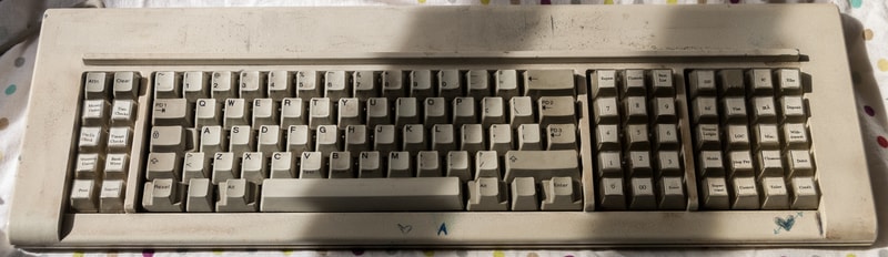

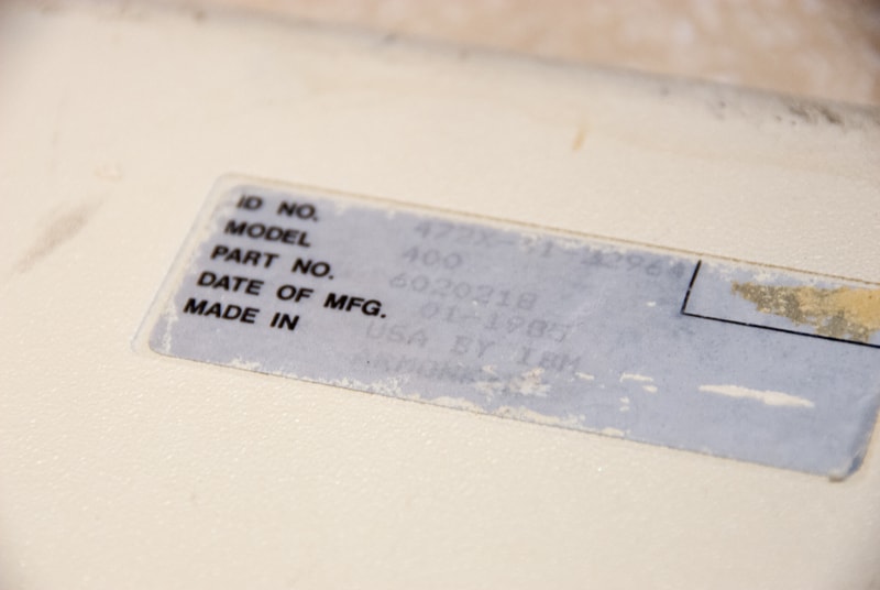
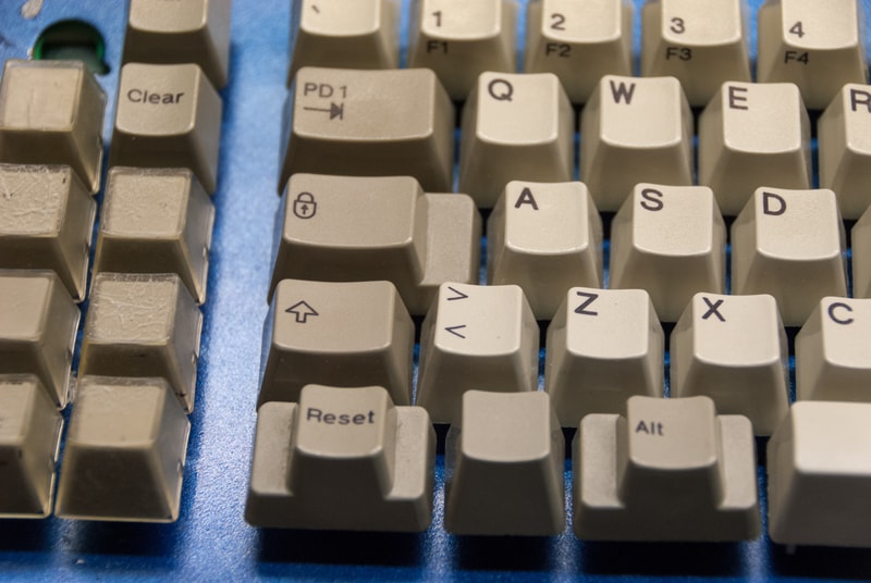
Out of the box, it was pretty damn dirty. Partially sticky, pen drawings on the case, peeling, chipping, and eroding paint, and grimy. Just what I expected from a bank teller’s keyboard. On the back the label was still intact. It was manufactured in the Armonk, NY factory, January 1985. There is also a stamp on the inside of the top case that says January 25, 1984, as well as a stamp on the bottom half of the case that says December 8, 1984. First impressions of typing on the keyboard were good. All of the keys felt and sounded like they were buckling smoothly, with all of the stabilized keys working properly.
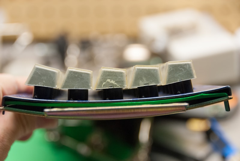
Soaked the keycaps in a bowl with warm water and laundry detergent for a few hours. Separated the windowed keycaps, and removed the labels. Everything looks great now, except for the tops of the windowed caps are a good deal yellowed, with some cracks in the casing.
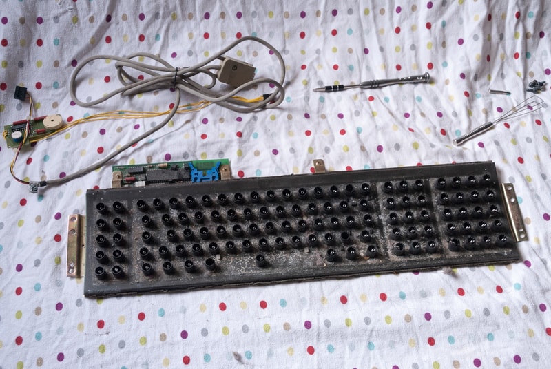
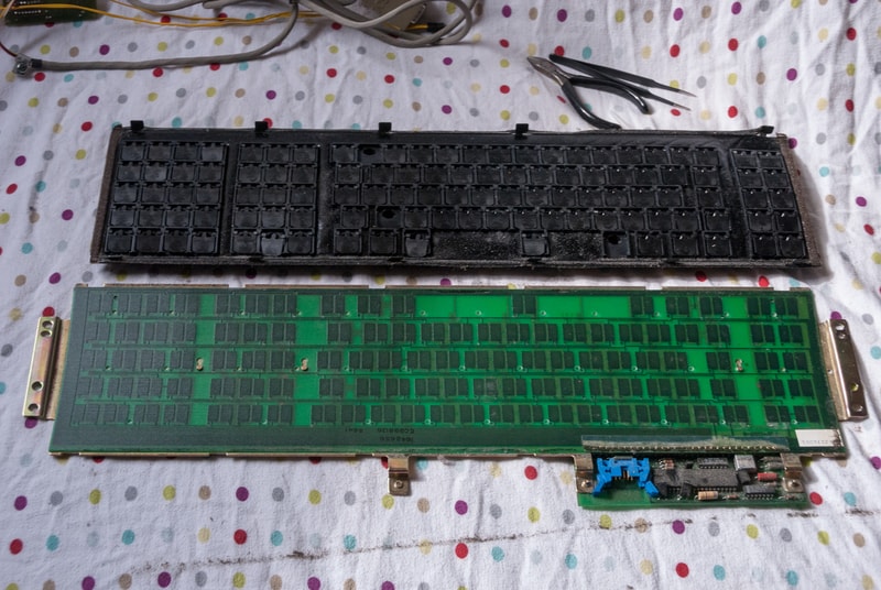
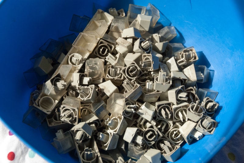
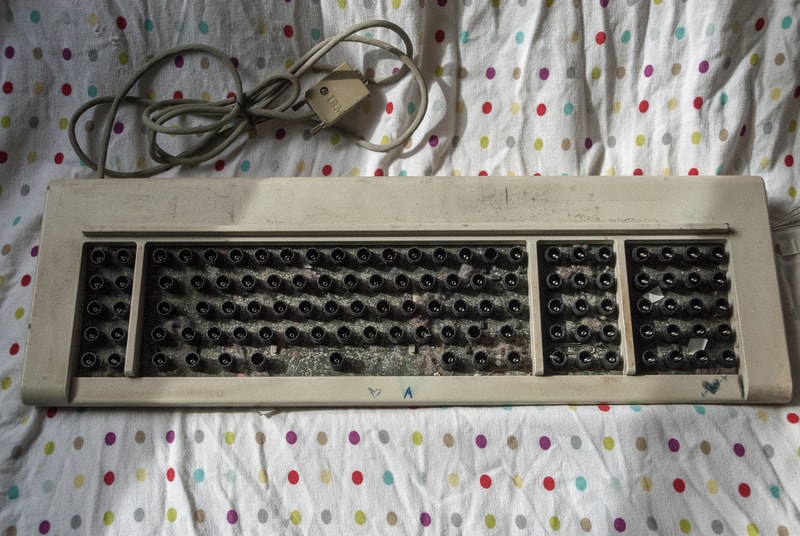
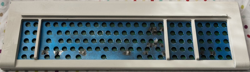
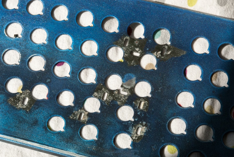
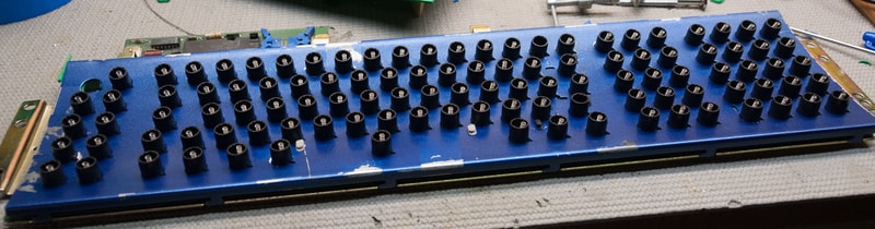
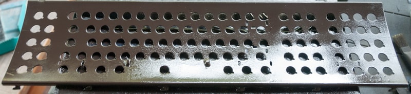
While this is the first time I have ever cracked the case of a Model F, with the amount of reading I have been doing here on these types of boards, I felt pretty confident I could do it. And sure enough, it wasn’t bad at all. The barrel plate was clearly a mess. It had corrosion and a bit of rusting, as well as crap sticking to it like crazy. The PCB is in excellent condition. Besides a minor possible issue (which I will get into later) it looks great. All of the flippers (flippies?), barrels were also looking great.
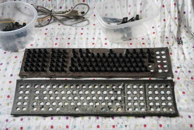
The foam however, was not okay. It was attached fine, but it was disintegrating. Its hard to describe, but some of the sections had no foam left at all. I tried to be as careful as I possibly could when removing the foam from the barrel plate, but in the end it had turned the sheets I had been working on (weird place to work I know, but that room had some good lighting for taking pictures) black with dust and bits of foam. While its not going to be easy, I am gonna have to replace the foam.
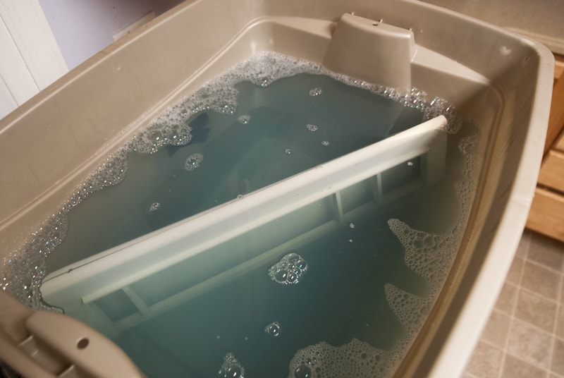
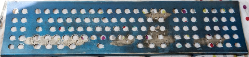
The next steps were to find a tub large enough to submerge the entire 12 pound case to soak it in detergent for a few hours. While it was soaking, I went and sanded down the barrel plate with some 600 grit sand paper. I got it as smooth and corrosion and rust free as I could. In order to keep it rust free, I taped up all of the stabilizers, and sprayed it with a few coats of Rust-Oleum, Stops Rust paint. I sanded in between each coat with 1500 grit, and gave it plenty of drying time. I am aware that it is blue, but it was the only adequate paint I could find at the time :laughing:
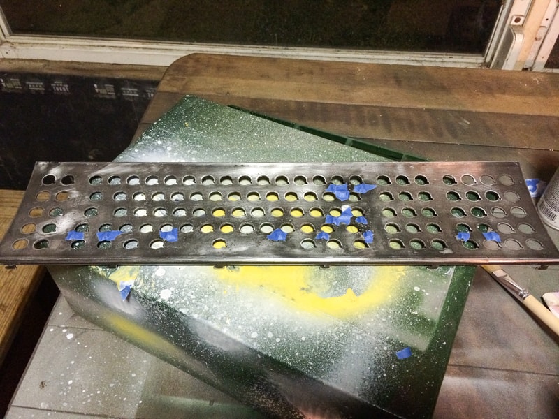
Finally, this is how everything looks after being washed, and sanded/painted. As you can see the paint does not look great. Some how it looks like I might have scratched a bit of paint off of the left hand side, and there is discoloring around the top. It looks a hell of a lot better then before, but still not perfect.

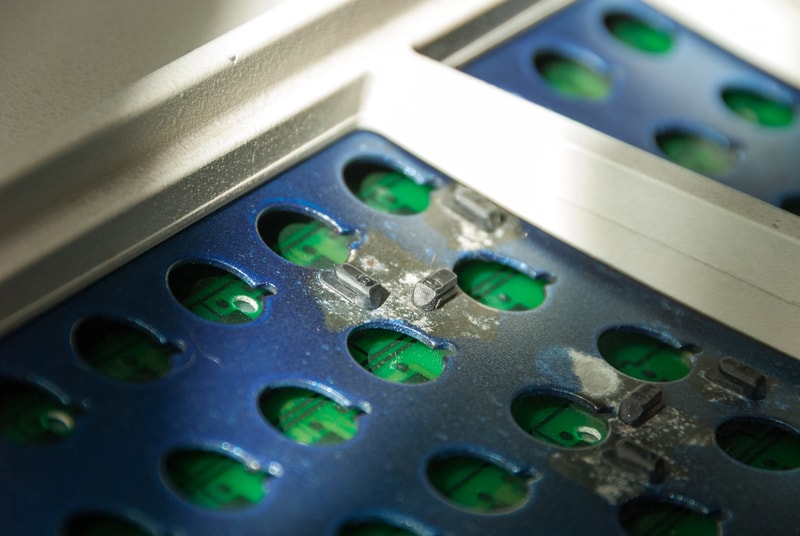
I mentioned that there was a tiny, possibly non existent problem on my PCB. It looks like a bit of the solder mask chipped away on this part of the pad. I understand the basics of how these capacitive switches work, but I can’t really tell if this small chip is really going to effect anything.
That is all the work I have done so far. I am still recuperating from all the spending I did last month, so it might be another month before I am able to continue work on this. I plan to buy some of Xwhatsits controller PCBs seperately through OSHpark, and all of the components, and assemble everything myself. I need to figure out what is the best type of foam to use, and then I need to figure out what I want to do about the case.
There are already a few threads here about the best kind of replacement foam to use in these Model F’s.
For example: This excellent thread
There are a lot of options to choose from. Any feedback on the foam mat, the PCB, or what to do about the case… Actually, any feedback at all would be greatly appreciated. Also let me know if the amount of pictures here was overkill, or if I should add the images into spoilers or whatever to make things load faster. I will continue to update this, when ever I make any more progress.
Post #2 - Sept. 30th, 2014
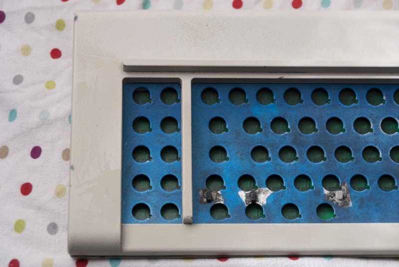
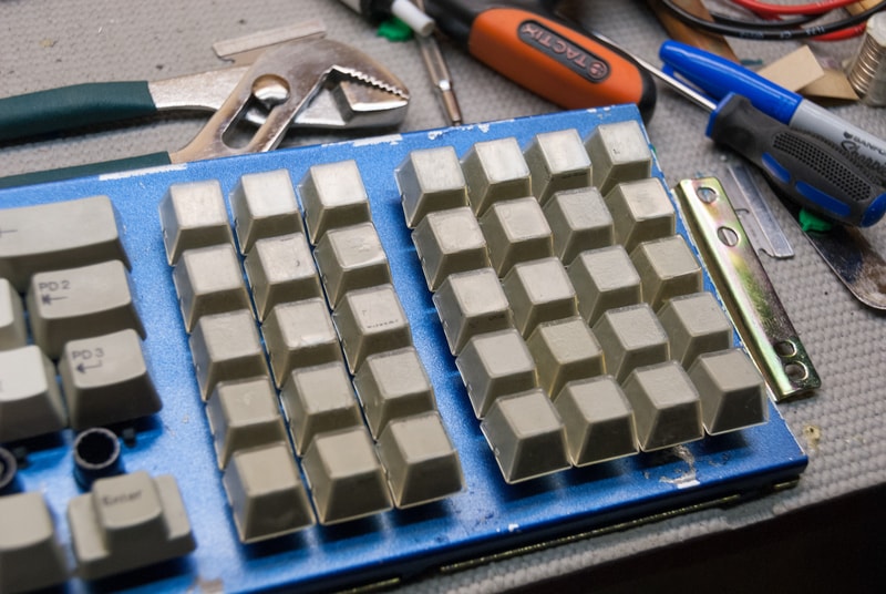
Just a quick update here. I posted this thread over on Geekhack, which I got some good responses. Including some advice from fohat.digs about removing the stabilizers. Seeing as I plan to update the layout of the board, there are quite a few extra stabs on the plate, and there is super heavy corrosion and rusting near each stab, I decided to pop them all out.
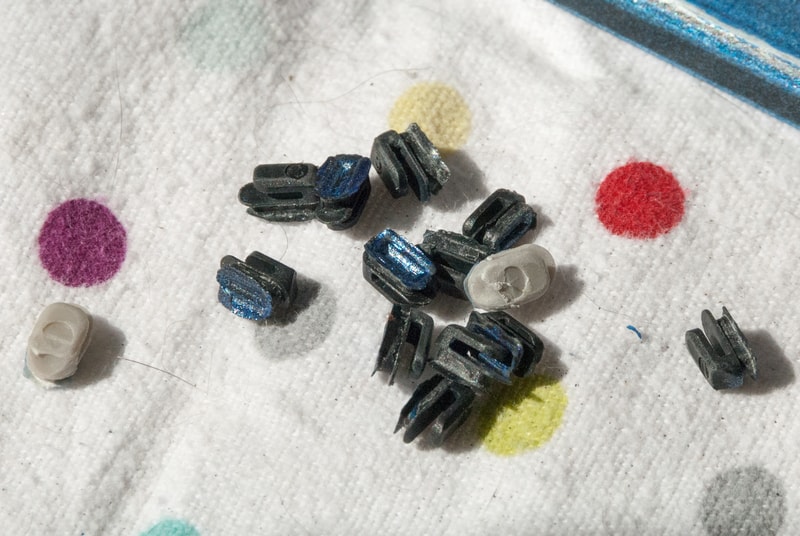
As you can see, it turned out nicely. I was super careful with everything, and in the end I only slightly “lost” 1/14 stabs. The one that lost its bottom flange plastic, still fits snugly into the plate though. I imagine a small dab of hot glue, and the stab will work just fine.
Because I am updating the layout, and there are a bunch of extras already on the board, I would be up to giving some away if anyone needs a couple. Sadly I need the space bar stabs though, as I only have 2, and according to fohat.digs, wire stabs haven’t been used since 1989…
I have decided that I will eventually be getting the case painted locally in (roughly) IBM Industrial: RAL 7030, as Andrewjoy suggested.
Post #3 - Oct 3rd, 2014
I realize that this thread has a ton of photos in it already, but I will show no mercy. I will continue to fill this thread with pictures, mobile users and capped bandwidth users be damned :devil:
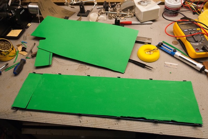
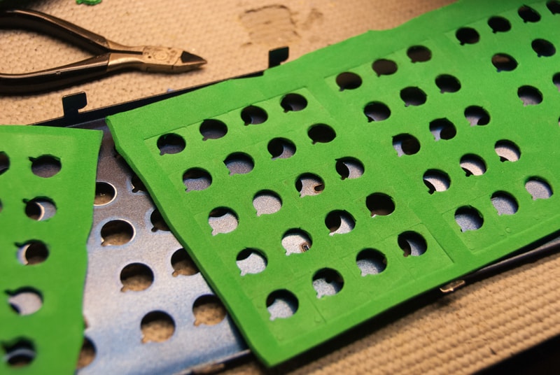
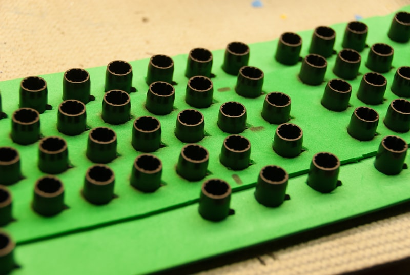
I made great progress the past couple days. I managed to quite easily tackle the replacement foam issue. Based on reading a bunch of threads, I chose what was not only recommended, but would be the cheapest and easiest to obtain. That would be .49 cent sheets of craft foam from the local craft store. I picked up $7 worth, and only used 2 sheets. Overkill at its finest.
I want to start by saying that I did everything manually, with scissors. I have the proper tools somewhere buried in the mess of my workshop, but due to impatience, I did just about this entire process using scissors and a razor blade.
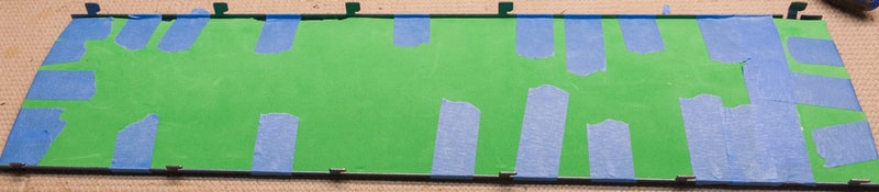
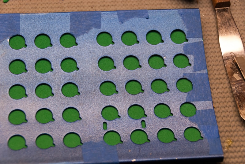
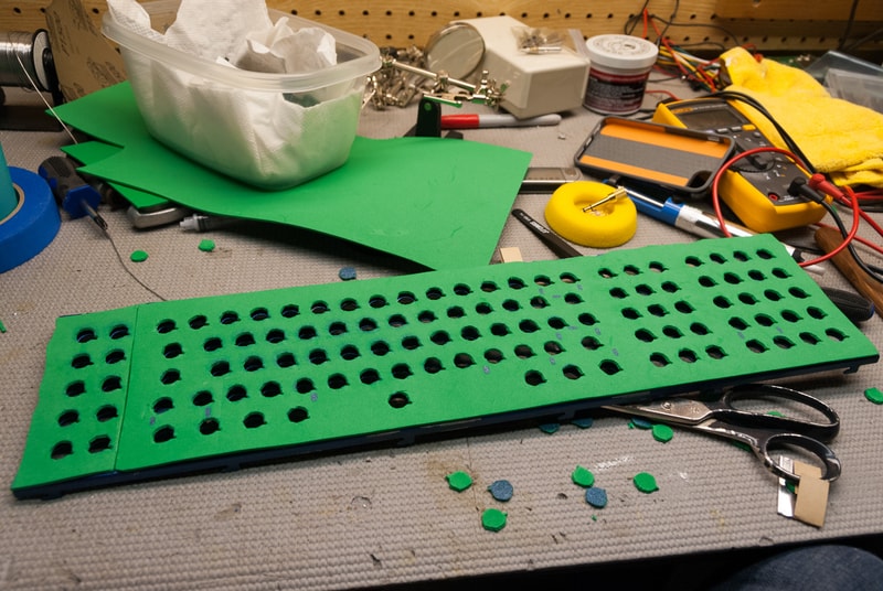
Cutting the foam horizontally was the first step. Getting it to fit into the edges of the barrel plate, was easy. The first thing that I noticed was that being such a huge ass keyboard, the foam that I bought would not reach the last (technically first if looking at it right side up) column of 10 barrels. So I had to cut out a separate block. I taped the felt down to the plate with what I thought would be safe, blue tape. Then I did a coat or 2 of paint onto the plate, leaving wonderful outlines on the foam.
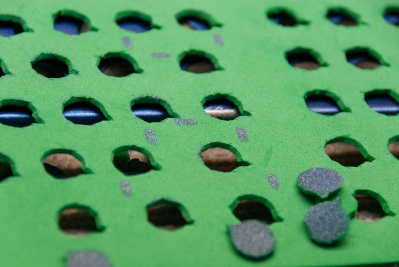
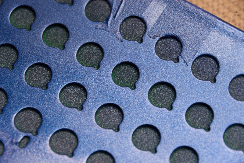
I proceeded to cut out each individual circle. At this point, I was planning on using my drill press to cut out each individual circle. I tried on the first hole, and it tore up the edges of the foam pretty bad, and it also meant I would need to cut out the small notch manually, anyway. The only x-acto knife I had was super dull, so that meant, and like I mentioned, my leather punches were buried, and I had no desire to go dig for them. In the end it took me about an hour exactly to cut out all of those holes. While they don’t look pretty, they hold the barrels perfectly, and I didn’t manage to screw any of them up.
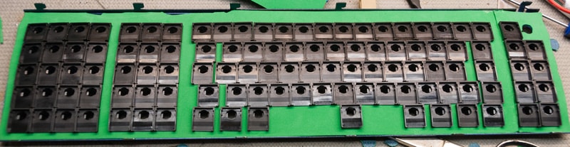
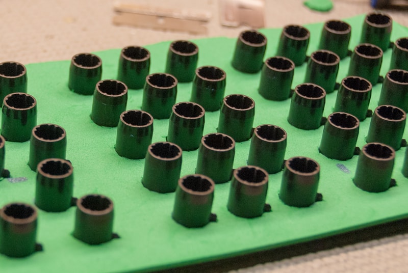
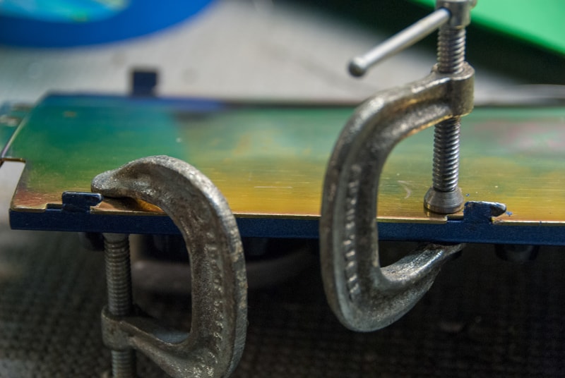
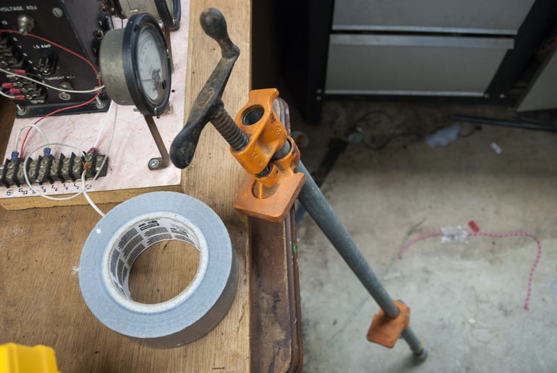
This part was the most tricky to figure out. I still don’t know whether I did this appropriately, but I do know that it works. After installing all the stabilizers in backwards (minus the spacebar) and popping in all of the flippies (including some in the wrong barrels), I needed to find a way to get the PCB onto the plate. The same thread that was fohat mentioned using craft foam, there was also discussion about using clamps for something. To be honest I did not read that entire thread, as carefully as I should. When I got to this step, I knew exactly what they were talking about with the clamps. These are the steps I used to very easily get the plates back together. I don’t have any more pictures of this process sadly:
- Lined up the PCB and the barrel plate, and hooked in the side of the barrel plate/PCB with the longer fatter metal tabs.
- On the side with the smaller thinner metal tabs, I took a pair of needle nose pliers and bent them back from the plate.
- Using clamps I tightened the PCB and plate together, until the PCB passed the edge of the tab.
- Then I bend the tab back into place over the PCB using pliers, and do that for all the tabs.
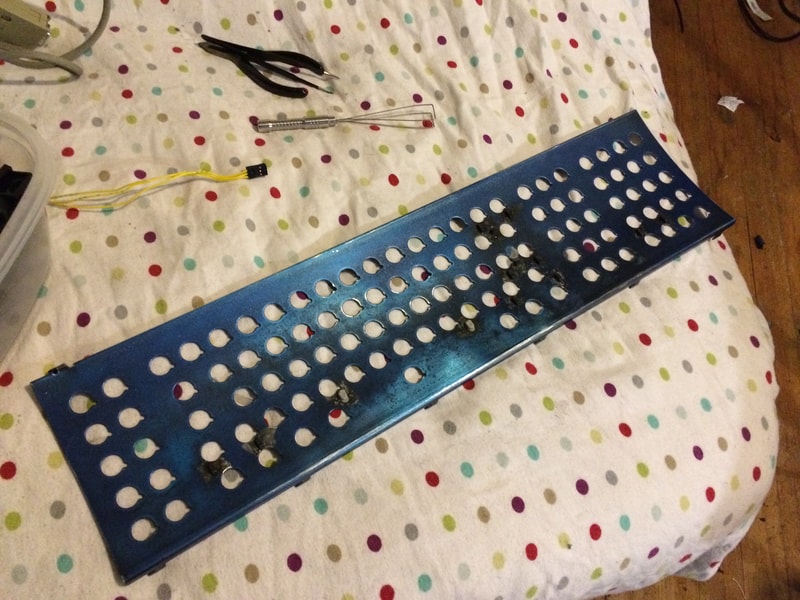
As you can see, the plate looks like crap. The paint got torn up for a couple reasons. The primary being the fact that I did not really give the plate time to cure. This probably only had 6 hours at most to cure from the last coat, to trying to assemble everything. The clamps, the blue tape, and a screw driver (inserting stabs) all proved to destroy the paint. For this reason, I highly recommend allowing any paint 3 days to fully cure (yes 3 whole days), as well as using heat shrink (or duct tape etc.) on the edges of the clamps. This should help to reduce the destruction of your beautiful paint.
I was impatient with assembly because I was already pretty sure I wanted to repaint the plate with a more drab color, and I wanted to test to see if that foam worked at all, or if I needed to get to work on something totally different.
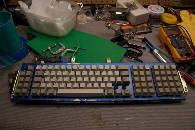
After assembling all of the keycaps, I noticed that the top and bottom row keys felt insanely sturdy and were surprisingly not all that pingy. The center 3 rows on the other hand felt very “light”, they pinged like a piano, and if you wiggled around the “F” key, R, D, G, C, V, R, and T all moved around with it. I also found out that I put a few flippers in the wrong spots for the stabilized keys, and some how I have managed to lose a single barrel+flipper, with no freaking idea where it went!
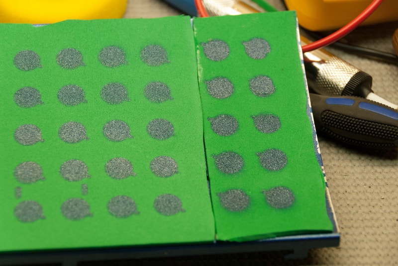
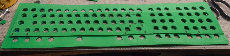
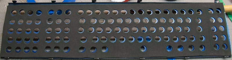
Opening everything back up, I found exactly what I suspected. There was not enough foam on the middle rows. You can see by the marks left in the top and bottom row, with hardly anything on the middle 3 rows! I have remedied this by cutting out a second piece of foam for the middle 3 rows.
I have also decided to repaint the plate with a nice Walnut color. I am also clear coating the plate, and it is currently drying in a nice spot, and will be curing for 3 days. I will not be reassembling everything until Monday.
I will close this project update with a question. I want to update my key layout on this board. Specifically I would like to lengthen the left shift, possibly do a HHKB style right shift, and extend the enter key. I would also like to replace all of the windowed keys. I want nav keys in the first block of 15, and then turn the block of 20 into a numpad, with something like F1-10 in the block to the far left.
What would be the best way to do that? I was originally thinking about just buying a Unicomp keyset for $30, but there is that whole quality issue there. Would it make sense to just buy and strip a Model M, or does Unicomp have decent enough quality? And what about the special size keys. To do the layout changes I am considering, are there any specific keys, not included in a stock layout that I would have to separately source?
Post #4 - Nov 6th, 2014
As some have probably read, I have successfully gotten my 107 key up and running with one of Xwhatsit’s controllers! Even though it worked, I am still a good ways from finished with it. Since starting this work log, I have realized the truly vast amount of content surrounding Model F restoration out here already. When I started, the photo aspect of this project was at the front of my mind, and recently I have been making progress, forgetting to take pictures. As the board nears completion, I will try and take more pictures. Anyway, here is what I have done and what I have learned:
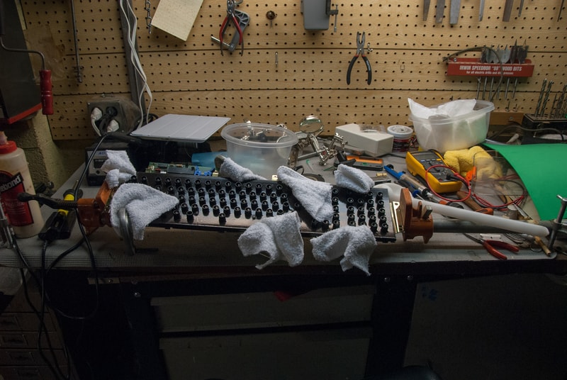
If I haven’t already stated it enough, I was very wrong about bending the metal tabs, in order to put the barrel plate and PCB back together. As Fohat pointed out, the PCB and barrel plate need to be force fit into place. As others have suggested, the best method is to use a really long clamp to hold the PCB. Then use a rubber/plastic mallet/hammer to smack the plate into place, and then bend the top left tab back over (the large tab is the only one that should/needs to be bent.
I have since realized that Hypersphere is right. When it comes to painting these damn barrel plates, you have to rigorously follow the directions on the spray can. He recommends doing 1 coat per 24 hours, with light sanding (1500 grit or so) in between each coat. Stick to general painting guidelines (you put on too much paint if it looks wet) and don’t put on too many coats. Then let the plate cure for a good 3 days before trying to reassemble it.
In addition, I found that wash cloths were ineffective for protecting the back PCB plate and the barrel plate from marks when clamping down the board for reassembly. This could be for an assortment of different reasons (types of clamps, binder clips, amount of clamping force, etc) but something I picked up from Quantalume was to use spare bits of foam on either side of the clips. I can confirm that foam works quite well.
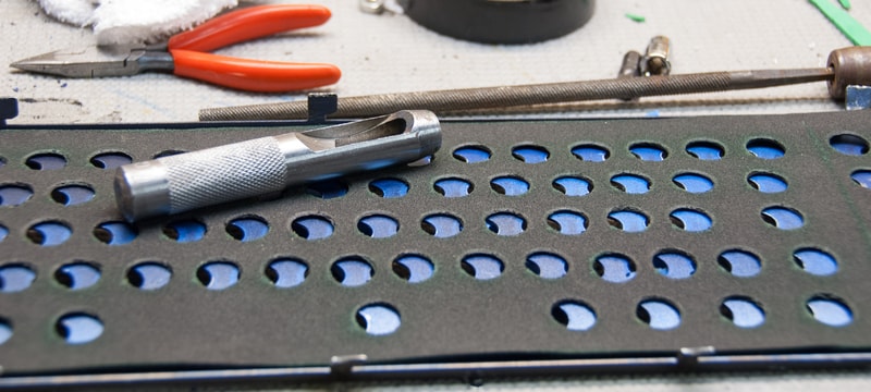
Don’t be an idiot like me. Use a leather punch for your foam layer. 5/8” worked perfectly for each of the holes, and only took me 20 mins to punch out all the barrels. Just make sure you have a softer piece of wood under the foam, and that you are not punching directly into a preexisting hole. Foam can tear easily.
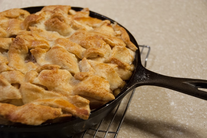
While I was waiting for my Xwhatsit controller I baked an Apple pie in a cast iron pan, from some left over apples we got from a local orchard. I didn’t really spend much time making the crust look nice, but it was damn tasty. And yes, I did eat close to the entire pie, myself, in the matter of 2 days (I know that’s what everyone was thinking :laughing: )
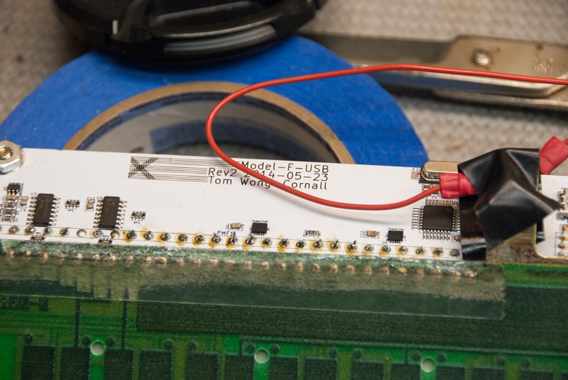
I need to clean up the excess solder flux, but it didn’t turn out… too badly. The heating element in my soldering pencil in my soldering station is still damaged. So until I order a new one, I had to use a Weller, “plug in the wall” iron, with no temperature control :surprised: Reckless I know…
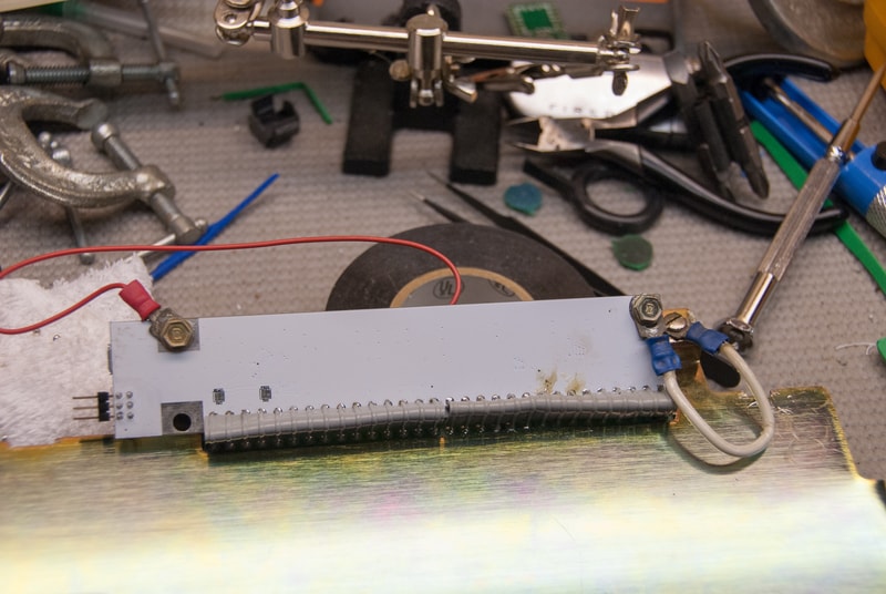
I have since cleaned up the excess flux, clipped the ends, and replaced the red jumper with a shorter one. I had a pretty difficult time lining up the controller, and once I had finished soldering everything, I realized that it wasn’t able to bolt into one of the tabs on the PCB - hence the jumpers on either side, to make sure it was grounded. It does fit into the case safely, with no strain, and everything functions properly. I may or may not try and make it look prettier, but it is a lesson for future boards. Make sure you get that ribbon cable safely de-soldered, and stripped, and ensure the controller bolts into a tab, before soldering.
Just some final comments on this update. I know the issue of foam has been beaten to death, but I will say that I have not had much of any luck using art foam. I believe it is just too stiff to work properly. I have tried art foam from both Michaels and A.C. Moore (a craft store on the East Coast) to minimal avail. 1 sheet of foam was just not enough. Middle barrels wiggled and pinged like crazy. 2 Sheets was way too much material, and using 1 sheet with a single strip of extra foam in the center row - worked, but still doesn’t compare to how perfectly this 1/16” Super Soft Weather and Fire Resistant Neoprene Foam worked. That’s the same foam that has been recommended plenty of times, by plenty of people.
I am going to be getting a Model M + an XT from Cindy soon. In addition to insert stabilizers from Unicomp. Next update will be final assembly. Long term update will be getting the case powder coated.
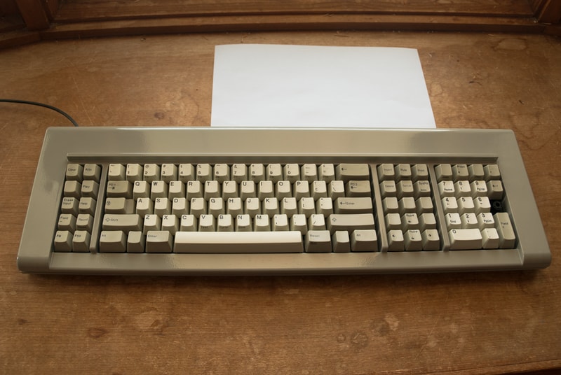
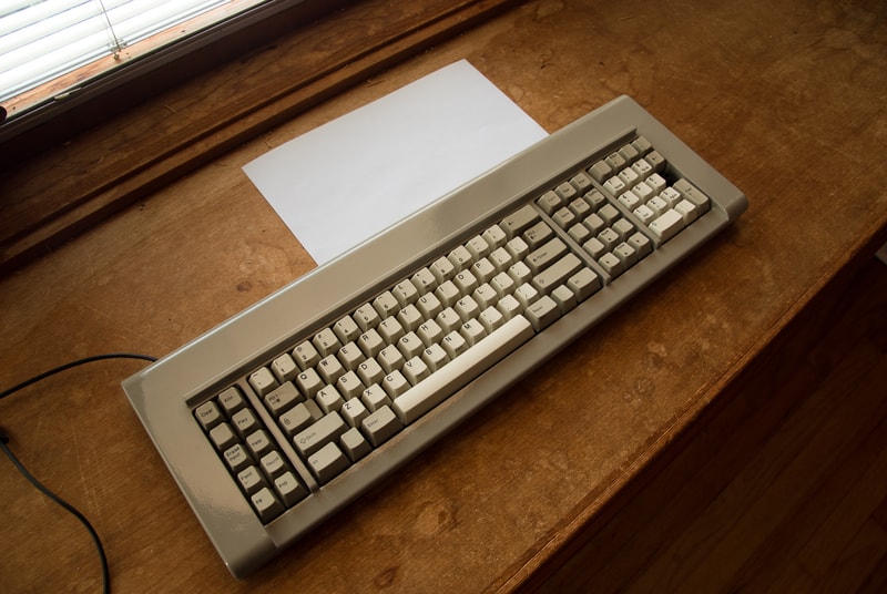
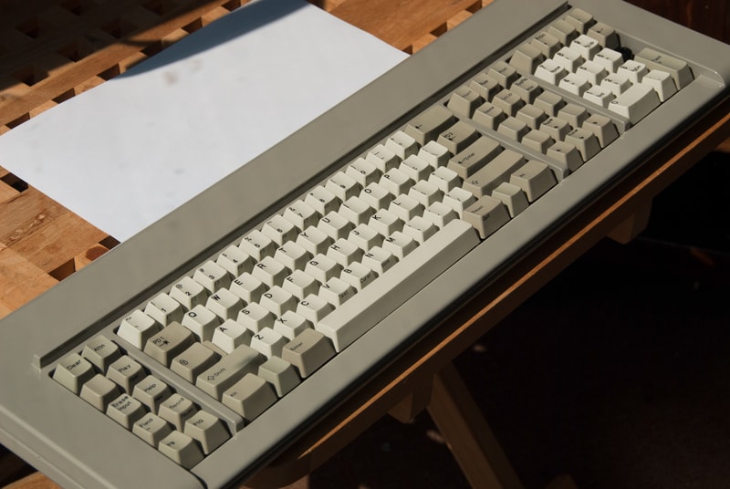
Post #5 - Sep 2nd, 2015 I never actually posted an official final update to my build logs I guess. The final piece of the puzzle was getting the case powdercoated and a proper modifier key for the numpad. A great user on Deskthority known as XMIT also had one of these keyboards, and offered to let me ship mine to him, and get them both sand blasted and powder coated. We settled on RAL 7030 Industrial Grey. It turned out remarkably well, and I still using this keyboard even today. In fact I am typing this on it right now.
I did however post these pictures of the finished product in a different thread